14 September 2010
Just as in automobile manufacturing, an increasing number of large-scale aircraft manufacturers, as for example Airbus, are delegating development tasks to their suppliers. The suppliers are usually forced to use the same CAD / CAM systems as their respective customers. The handling of such systems, however, is rather complex. For this reason, intuitive CNC programming is rendered more difficult since shop floor employees have the necessary manufacturing know-how, but usually their computer skills lack behind. Pfalz-Flugzeugwerke GmbH (PFW) has found a solution to this problem: The CATIA models they design are converted into TopSolid geometries, which are then used to create milling programs with Missler’s CAM software.


Today, Pfalz-Flugzeugwerke GmbH carries the same name as in 1913 when military aircraft were produced at the Speyer location. In between, however, the company was newly founded after World War II as the Ernst Heinkel-Fahrzeugbau GmbH. Since then, the company has changed owners several times causing name changes as well. From 1964 to 1983, the company went with the name Vereinigte Flugtechnische Werke VFW, and from 1969 to 1980 it was called Vereinigte Flugtechnische Werke – Fokker GmbH. After that, the company was part of Messerschmidt-Bölkow-Blohm GmbH until Deutsche Airbus GmbH took over in 1991.
Under the umbrella of the Deutsche Airbus GmbH, which later became Deutsche Aerospace Airbus and then Daimler-Benz Aerospace Airbus GmbH, the Palatinate aircraft builders manufactured body shells, structural assemblies, and equipment components. When in 1997, the Airbus site in Speyer was in danger of being closed down, the company's management and employees took over. Today, PFW employs approx. 800 staff and its annual sales amount to more than EUR 130 million (financial year 2000). With its US location, the single source supplier for Airbus components opens the door to the American aircraft manufacturers.
Suppliers in the aviation industry are subject to enormous time pressure since aircraft manufacturers constantly speed up the aircraft assembly process. At the same time, customers are given the opportunity to decide on the final equipment of their aircraft until only a few weeks before delivery. Therefore, suppliers of certain system components must have exceptionally short lead times. The economic turmoil hitting some airlines in the wake of the September 11 attack is adding further to this time pressure. Insolvent Airbus customers, as for example Swissair, have canceled orders for airplanes that were due for delivery. These planes now need to be modified in no time to be able to sell them to other customers.
"The logistics business has been exploding after September 11," says Peter Hammann, supervisor at the control center for cargo loading systems and structural components assembly at PFW. PFW supplies Airbus with piping and additional tank systems, structural assemblies, and complete cargo loading systems. All of these products need to be adapted to aircraft type and customer requirements. Swissair, for example, preferred fully automated solutions. Other airlines operate in cheap labor countries and prefer manual cargo loading systems. "If the customer changes, we need to be able to trace the components that have been assembled in order to provide the necessary replacement parts as quickly as possible," explains Hammann.
In contrast to piping systems, the manufacturing process of cargo loading systems has a high manufacturing depth. PFW obtains electronic drive systems and movable parts such as brake rollers or stop pins built into roller conveyors from other suppliers, but these parts are completed and pre-assembled at the Speyer site. As a result, if certain components have to be replaced, a large number of process steps still need to be executed by PFW.
More responsibility for PFW
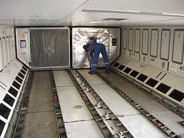
Formerly, cargo loading systems used to be designed by Airbus itself and were then manufactured in Speyer. Today however, the responsibility for new developments has shifted to the supplier. For the new wide-bodied Airbus 380, PFW will not only design and manufacture the cargo loading system but will also be responsible for the documentation, the system's approval by the German Civil Aviation Authority (Luftfahrt-Bundesamt, LBA), and the system assembly at the Airbus site in Hamburg – provided that the contract is awarded to the former Airbus plant. The tendering process has not yet been concluded.
Their new role as development partners means substantial investment for the suppliers. To be able to meet Airbus’ high requirements, PFW has already invested some 100,000 EUR for the concept and the prototyping of the new cargo loading system. Due to its weight, the A 380 will be equipped with additional landing gears that will be integrated into the sides of the aircraft's body, thus reducing the loading space in the middle part of the aircraft. To use the loading space regardless of this constriction, the containers need to be turned at the entrance area and moved lengthwise into the body of the A 380.
In recent years, PFW has established its own design department to meet the new challenges in product development. Choosing a system became superfluous after Airbus decided to perform the entire modeling process in 3-D using the CATIA software. PFW had to go along with this decision. However, in its interconnected manufacturing and tooling design departments, PFW uses Missler’s TopSolid and TopSolid'Cam solutions.
"Originally, we wanted to have one CAD / CAM solution for design and manufacturing, but when Airbus took so long to decide on a solution, we just went ahead and introduced TopSolid'Cam in 1999," explains Hammann, who abides by his decision even after the introduction of CATIA. "I want the CNC programming to be done in the manufacturing department. It is not enough to create the milling paths based on the geometries. This step requires special technology. For this job, I need people who know how to operate the machines, people who have received extra training – but CATIA is not the right tool for them."
Milling from solid blanks
The most common manufacturing methods in Speyer are milling, drilling, and riveting. Aluminum parts, except for profiles, are milled from solid blanks since the strict aviation safety regulations prohibit the use of pressure die-casting parts. Even without such regulations, tool manufacturing would not be cost-effective in most cases, as only a small number of parts is needed. "Orders for more than 100 pieces are very rare," says Hammann. "We sure put things through the mill. We have parts where the degree of chipping amounts to 95%, i.e. from 12 kilograms of raw material, only 600 grams will remain."
Formerly, milling paths used to be programmed directly at the machine or with a simple editor. The limitations of these two methods soon became obvious: parts became increasingly complex in order to reduce weight to a minimum without compromising functionality and durability. "In aircraft design, weight is the measure of all things," says Hammann. "For the A 380, the parts are planned to be lighter still, but, at the same time, they need to be able to bear heavier loads. The profiles of the roller conveyors will be equipped with hundreds of relief holes at the edges, which reduces their weight by a total of 20 kilograms. Generally, any superfluous material will be removed to reduce weight, which sometimes results in pretty peculiar shapes."
Safety, however, is more important than reducing weight – especially in the aviation industry. If a cargo container or even an additional tank comes loose during take-off or landing, the plane will certainly crash. For this reason, the requirements regarding materials and manufacturing methods are very strict, as Hammann's following example points out. "Usually, the shop foreman decides which cooling lubricant is used for a machine. In our case, the LBA tells us which cooling lubricant to use."
The increasing complexity of the parts required the purchase of new milling machines and machining centers. In order to use the new machines efficiently, PFW also needed a powerful CAM system. Two systems were short-listed, one of them was the Missler software with which Hammann had already worked on an implementation project in another company. Their functional range and the better price/performance ratio turned the balance in favor of TopSolid and TopSolid'Cam.
"The software needed to be easy to learn," says Hammann. "Most important were graphical simulation functions since the new milling machines use a lot of water so that the operator cannot see a thing. He only hears the crash when it is too late. Today, the machines are faster during the operation than they were between operations 10 years ago. The operator does not stand a chance to react in time. Therefore, we have to make sure that nothing can go wrong." With PFW's short lead times, downtimes become impossible. Some of the machines run on a 24 hour basis.
Finding a competent partner
Trying to avoid large system houses, Hammann was looking for a small but competent partner nearby who would also be willing to customize the postprocessors at a reasonable price. Over the years, PFW has acquired many different machines with diverse control units, some of which are rather unusual, as for example the machines for manufacturing seat slides or roller conveyors. "A large software house would not have customized a postprocessor for a single machine, or even if, the price would have been beyond our reach," says Hammann.
West, a Saarbrücken-based system house, turned out to be a suitable partner for PFW. The Missler sales partner West did not only implement the software, train the staff, and provide support, the company also customized the postprocessors, which was not always an easy task. "Our profile milling machines are customized to our needs," explains Hammann. "An arm is attached to the spindle, causing the drilling process to run backwards. As a result, the direction of rotation and feed changes. Furthermore, the zero point shifts by 200 millimeters. But how do I explain this to my computer?" Currently, controlling the five-axis machine sometimes causes difficulties, but Hammann is confident to be able to solve this problem in collaboration with West.
The manufacturing CAM installation includes two TopSolid'Cam workstations, but will be expanded by a third station if PFW wins the Airbus 380 contract. The software is installed under the Windows 2000 operating system on PCs that basically form a network within a network. The PCs have access to the CAD data from the design department and also retrieve their own data from the server. External control of both computers, however, is no longer possible as the automatic Outlook and Office updates frequently caused problems. In addition, the Microsoft programs slowed the computers down to such an extent that the software had to be installed on separate workstations.
Flawless CATIA interface
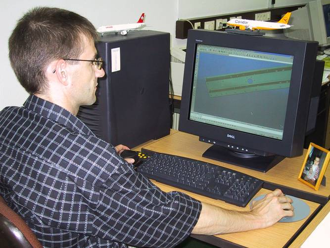
The manufacturing specialists at PFW use Missler’s CAD/CAM software mainly for programming milling operations. CAD data from the design department that have been converted into TopSolid geometries by the CNC programming staff using the efficient CATIA interface form the basis for these operations. "I position the models in a way that as few fixtures as possible are needed for the milling operations. Then I define the milling strategy and provide the required conceptual design," explains Dirk Martens, one of PFW's two CAM specialists. Usually, the machine operator in question is also present and makes suggestions.
In order to better understand the parts and to avoid subsequent changes, the CNC programmers discuss the parts with the designers. Sometimes, the programmers suggest changes to facilitate the milling process. Generally, part geometries are not or only very rarely modified in TopSolid, unless the changes are minute and the part's programming has already been completed. Due to the full associativity between the two modules, a simple mouse-click is sufficient to update both programs.
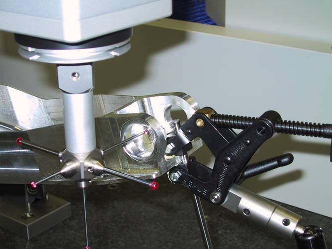
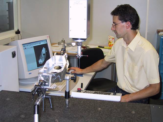
The TopSolid models of the parts are not only used for programming milling operations but for quality management as well. A short time ago, PFW has installed a new Zeiss measuring machine to quickly check the initial samples in 3-D. These measurements enable the shop floor staff to immediately mill more parts if the quality is acceptable. As the measuring machine cannot read CATIA data, an STL file of the TopSolid model is created and then compared with the physical measurement data.
Powerful simulation functions
The manufacturing staff were able to work with the CAM software after only one week of training, though their productivity was still limited. "Mastering such a tool is not an easy task. Therefore, we gladly invested in user training," says Hammann. "It does not make sense to spend millions on new machinery, but to try to save a few thousand Euros on training expenses." According to Dirk Martens, mastering TopSolid'Cam is easy but still impossible without training, especially since new features are added to each new version.
The Missler CAM software covers all functionalities required by PFW. "Automatic functions included in the software support the user in defining milling strategies," says Martens, "even if it would sometimes be faster to manually add a contour to the profile to be processed and to tell the program what you intend to do. You have to weigh up whether you want to use the automatic functions or not."
Martens considers the extremely reliable simulation functions one of the key TopSolid'Cam features. "Provided that machine, tool and fixtures are integrated on a one-to-one basis and that the postprocessor is able to accurately realize the program as we simulate it on the computer." The CAM specialists at PFW first had to simulate the spindle structure in TopSolid as the machine manufacturers do not provide 3-D models to their customers. West has adjusted the software in a way that enables the use of modified cutters, i.e. the milling paths will be corrected accordingly.
It is possible for the user to view the amount of material removed after each step by having the program recalculate the raw part's geometry. One thing Martens finds fault with is the time the program needs for processing some of the machining steps. "Another small shortcoming is that you need to recalculate each machining step if you change only the rotational speed or the feed of the first tool."
Faster and more precise
In Hammann's opinion, employing Missler’s CAD/CAM software results in shorter lead times, even if the exact amount saved cannot be specified. CAM processing of complex parts is doubtlessly faster than manual programming. However, the benefits can only be reaped if the software is used along with the new machines. Hammann uses the following example to explain his point of view: "By using the CAM software along with the new machine for manufacturing the housing of a cargo door latch we were able to cut manufacturing time by 60%. One of the reasons for this time cut was that less fixtures were necessary. At the same time, accuracy was improved as fixtures cause small deviations every now and then."
By Michael Wendenburg, Sevilla
Photos BG Concept Marketing Communication
Meer informatie nodig
EEN VRAAG OVER ONZE PRODUCTEN OF OPLOSSINGEN?
Vind uw dichtstbijzijnde verkooppuntContacteer onsVraag een offerte aan

