14 september 2010
Cutting and shaping tools for modular construction and devices for machining and assembly. Never before has sheet metal been as widely used as it is today. This has been made possible by improved processing techniques and by new materials. An integral part of the perfect sheet metal process chain is also, of course, the right CAD/CAM system. At Pockauer Werkzeugbau Oertel GmbH (PWO), the system they have chosen is TopSolid from Missler Software.

TopSolid Growth with CAD/CAM Know-How
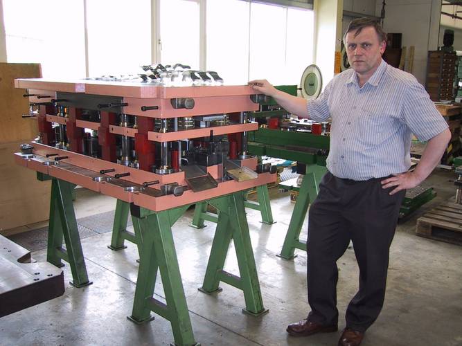
“90% of PWO’s activity is related to the automobile industry” states company boss, Matthias Oertel. The company produces cutting and shaping tools with up to 800 mm in length (progressive die tools), and with follow-on tools up to 3000 mm long for modular construction and devices for machining and assembly. Amongst other things, the tools are used for manufacturing levers, hinges and attachments for doors and shutters, along with parts for seat adjusters, gear components, and so on.
“By covering the process chain from end to end, all under one roof, we can cater to the individual wishes of our clients at a highly cost-effective rate," Mr. Oertel goes on to say. The process chain is supported by an integrated CAD/CAM system from the moment the customer data comes in right through to the post-processing of the NC programs. PWO opted for TopSolid from the French supplier, Missler Software, back in 1996, with the TopSolid reseller West installing it and providing the technical support.
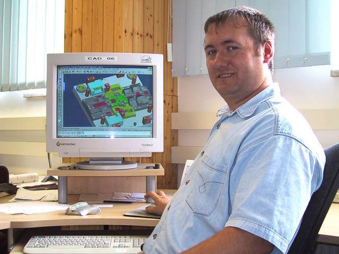
To describe PWO as a power user of TopSolid would be no exaggeration. Almost every possibility of the software is exploited, taking up twelve workstations in all. The CAD/CAM process chain comes into play when the geometry is supplied. TopSolid has a range of interfaces enabling geometries to be imported from or exported into other systems. These include Catia®, Pro/Engineer®, Solidedge® und Solidworks® as native interfaces and IGES, STEP, DWG, etc., as standard interfaces. According to Mr. Oertel, these interfaces “have been significantly improved in recent years and today they run without a hitch.”
The next step is the generation of a strip layout (placing the unrolled sheet metal on the stamping strip). The sheet metal functionalities of the CAD/CAM package help with this. Once the strip layout is approved, the actual tool construction can begin. First to be designed are the active parts (i.e. those that are actively involved in the cutting, bending and reshaping process), followed by the plates, columns, expansion capacities, etc.
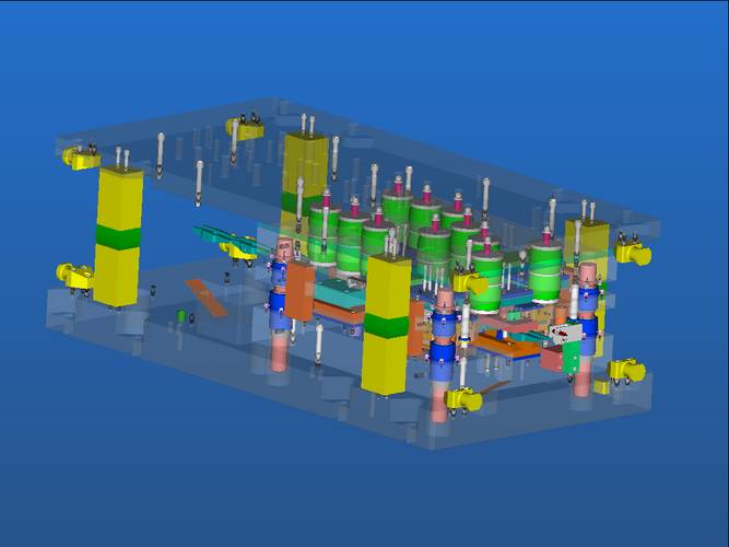
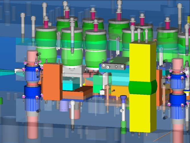
PWO constructs everything in 3D – down to the simplest part – in order to acquire a complete virtual model that continually serves as a reference for all progressive work cycles. The tools are constructed in modular fashion, with the system thus allowing a clear component structure to be created.
The tool makers make excellent use of the system’s parametrics. In Mr. Oertel’s words: “The parametrics can be of great use if the tool maker is capable of using them skilfully.” He gives as an example changing the undercut of a tool in order to compensate for sheet metal springback. “If, when running in a tool, we notice that the springback is not as expected, we have to change the undercut angle. This theoretically means modifying all surfaces involved and involves a time frame of two to three days. However, if the parametrics are properly set up, the same work can be done in ten minutes, just by feeding in a few parameters!”
PWO constructs its tools as far as possible using industry standard components, but needs in addition a wide spectrum of proprietary standard parts. To this end, a comprehensive proprietary library has been built up, which is of course kept up to date, and which pays for itself by dint of its frequent use.
When 3D construction is complete, technical draftspersons produce a derived 2D drawing, which is still required for customers, their own workshop and, where necessary, for subcontractors. In parallel to this, NC programming begins. Since, in this system, CAD and CAM are integrated in one core, there is no data loss or inconsistencies, and this helps minimize the NC programming costs. The NC programmer uses the system to generate NC paths, roughing, finishing and residual region milling and to implement an NC simulation. This means that the workshop obtains finished NC programs, where there is no longer any need for last-minute, rushed adjustment and optimization.
At PWO, however, only the 3D parts are programmed for 3-axis milling with TopSolid’Cam. All 2D parts are milled and programmed in the workshop. To date, this has been perceived as the fastest way of proceeding. All that then remains is the post-processing for the 3D parts, and then you have done your journey “to the end of the idea”, as Missler Software suggests in one of its brochures.
Along this process chain, Matthias Oertel and his colleagues value above all: “the high efficiency and easy handling of the system. If we had the choice to make over again, this is still the system that we would go for.”
Meer informatie nodig
EEN VRAAG OVER ONZE PRODUCTEN OF OPLOSSINGEN?
Vind uw dichtstbijzijnde verkooppuntContacteer onsVraag een offerte aan
